Water Treatment System at an Aeronautical Launch Center.

MAE2 was awarded a project after a competitive bid process to build a water treatment system at a former component cleaning and refurbishment workshop at an aeronautical launch center.
The site had been a parts cleaning facility that used chlorinated solvents such as Trichloroethylene (TCE) to refurbish components. The consultant’s goal is to extract contaminated groundwater from 3 wells at the end of the plume contamination area and strip the TCE from the extracted groundwater. The clean water is then re-injected into 8 injection wells to help control the groundwater flow and prevent additional growth of the contaminated plume.
Former component cleaning and refurbishment workshop at an aeronautical launch center
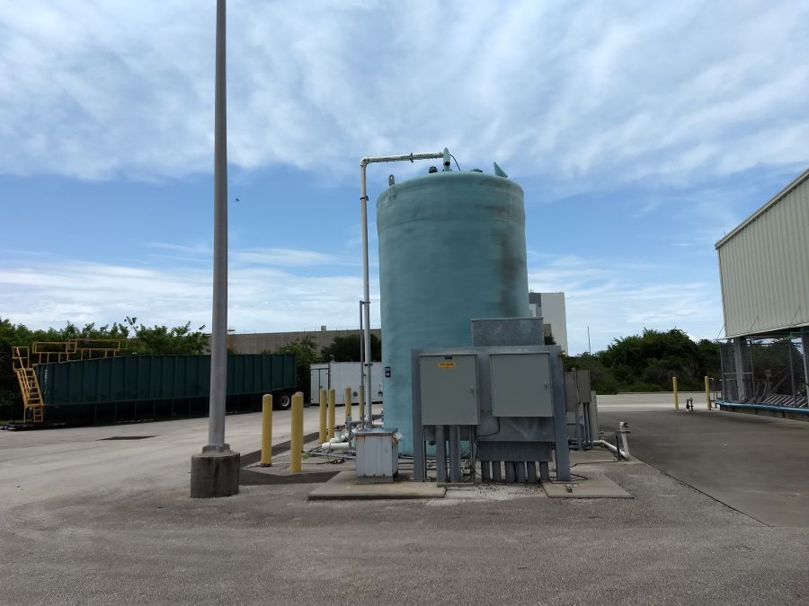
The water treatment system contained a three point groundwater extraction manifold. Groundwater is pumped from three wells using electric submersible pumps. Each manifold point includes individual water flow meters to record gallons per minute from each well. The manifold header is plumed through two bag filter housings and then to a 300 gallon inlet EQ tank. The bag filters remove any suspended solids and sediment from the groundwater.
An inlet flow transmitter displays total gallons pumped and the GPM flow rate. The water is pumped by a centrifugal transfer pump from the EQ tank to a Stainless Steel removable tray air stripper. The EQ tank and air stripper both include water lever transmitters that show the current water level and allow user adjustable pump on/off and alarm set points. After the water is treated in the stripper it is pumped by another centrifugal transfer pump through two more bag filter housings to remove any remaining sediments or solids to the injection manifold.
The manifold has a groundwater flow totalizing transmitter and seven individual injection legs. Each leg has a solenoid valve for on/off and alarm control, a pressure transmitter and an individual water flow meter.
The water treatment system is built inside an 8’x20′ custom steel building with water proof secondary containment and a floor sump alarm. The building also includes air conditioning to help the equipment and controls operate in the local ambient temperature.
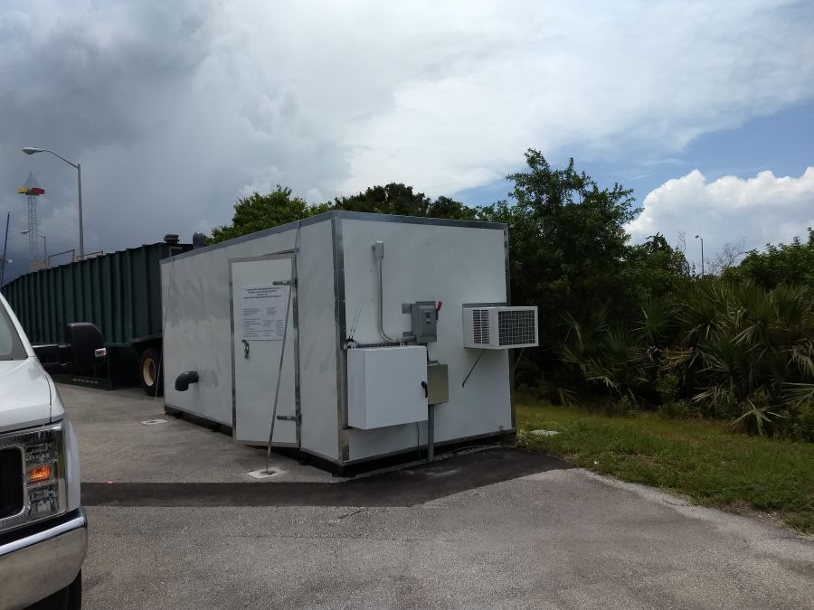
The water treatment system is built inside an 8’x20′ custom steel building
The system controls include a PLC based panel with touch screen controls and full web based cellular telemetry control and alarms. The controls allow the consultant to view and change all of the systems setting including pressure, flow, and level.
Components used in this system:
Centrifugal transfer pump
Bag filter housings
Removable tray air stripper
PLC control panel