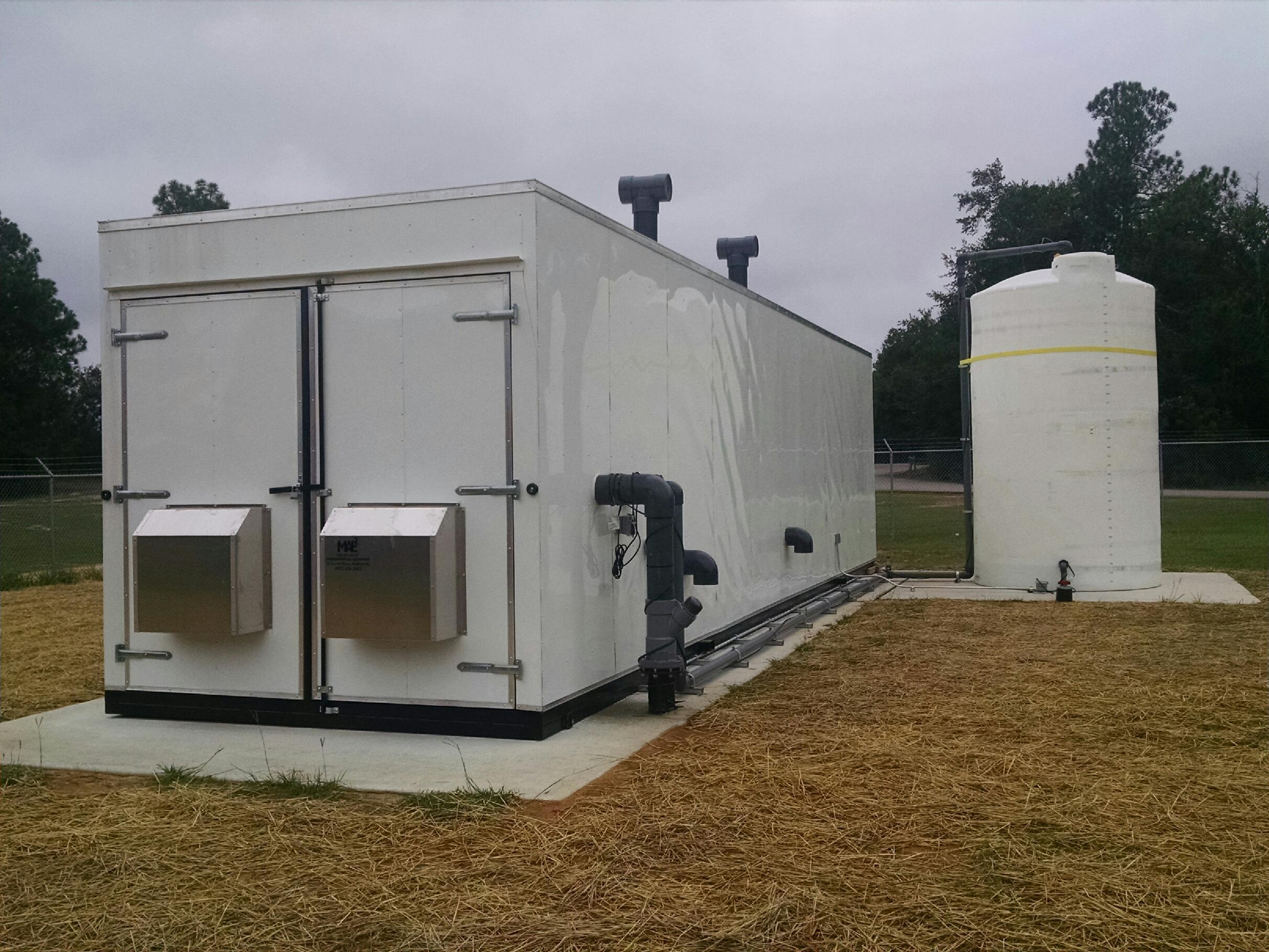
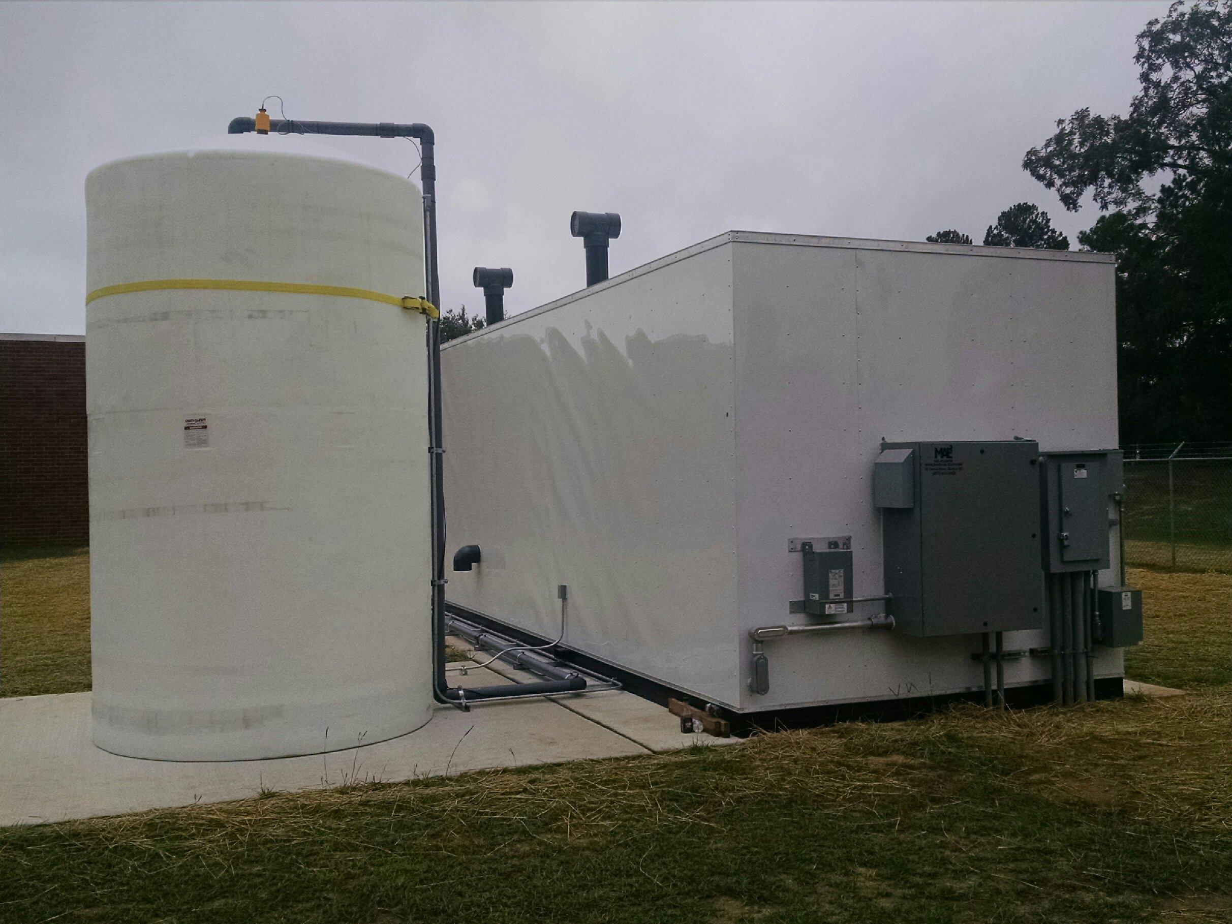
Project Summary
Municipal Landfill Project to Remediate PCE, TCE, Vinyl Chloride and Methane
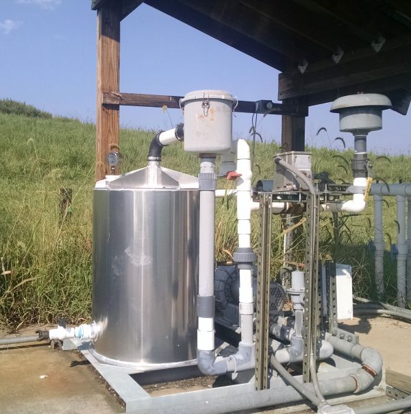
MAE2 has a full range of systems for recovery of landfill methane and VOC contamination.
Landfill systems operate in some of the harshest conditions and must be designed with those conditions in mind. MAE2 has the experience and capability to build a landfill gas system for your specific application. Blower sizing, material compatibility, and NEC electrical classification design are all critical to the success of your project.
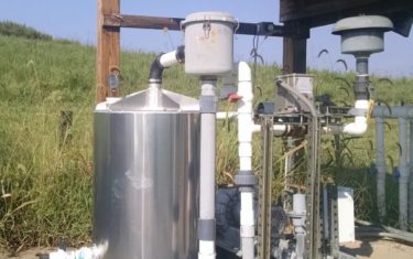
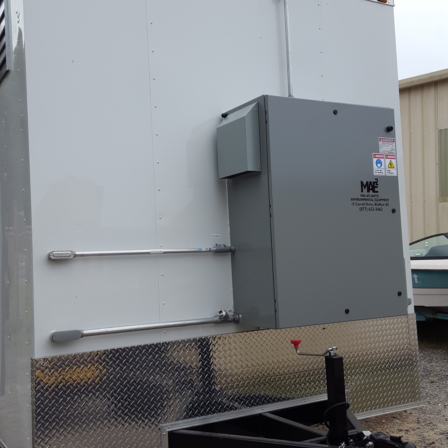
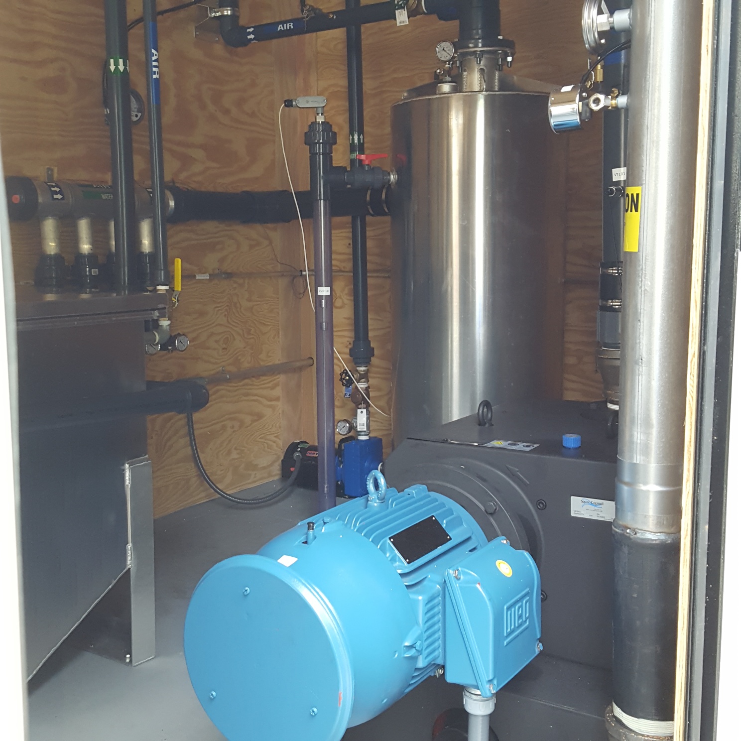
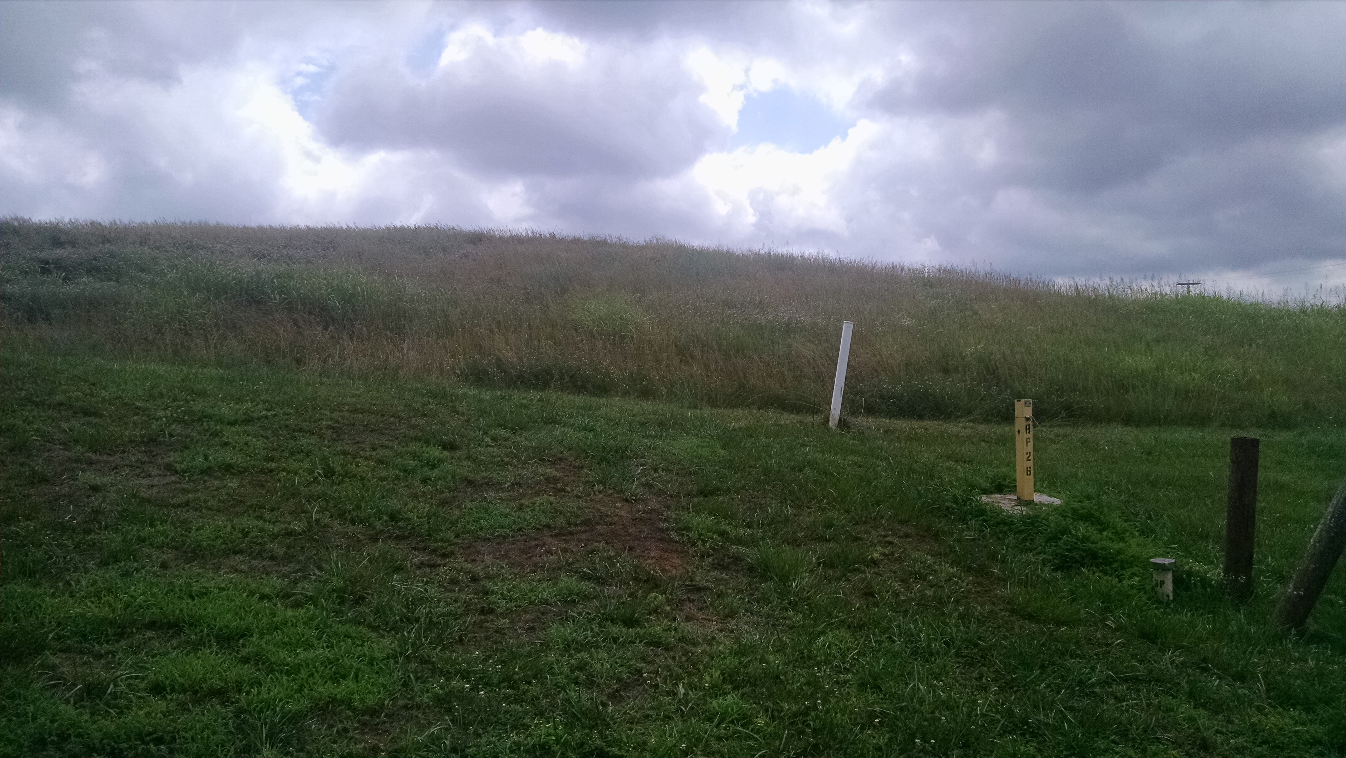
MAE2 was contacted by a municipal landfill to replace the main components of an existing blower system that operates within a landfill cell that is contaminated with PCE, TCE and Vinyl Chloride along with methane. The blower extracts the contaminated VOC’s and methane and then a propane enhanced flare destroys the contamination. The blower had failed and the vapor liquid separator had corroded from exposure to the elements and the solvents.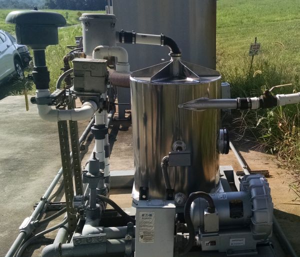
MAE2 recommended our Marine Grade Aluminum Vapor Liquid Separator to offer better protection from the corrosive VOC’s and the exposure to the weather.
MAE2 selected a regenerative blower based upon the system performance needs and the existing site conditions. The landfill was able to benefit from a lower cost blower selected to meet their current needs rather than replacing the existing blower with the same model. MAE2 assisted with the connection and integration of the new equipment into the existing system and provided complete start up and testing. MAE2 was able to use our experience to help this municipal landfill operation select and implement a cost-effective solution that will keep them operating trouble free for years to come.
This Landfill remediation project uses the following components and subsystems
Regenerative Vacuum Blower
Marine Grade Aluminum 60 Gallon Vapor Liquid Separator
MAE2 Selected for a second Air Sparge System at an Aeronautical Launch Site
This system, for a different customer, will include approximately 300 wells spread across the site
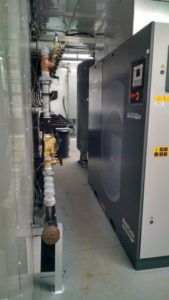
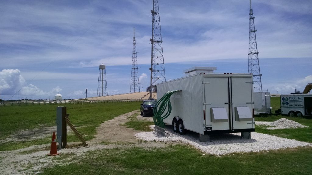
MAE2 was again selected after a competitive bid process to build and start up an integrated Air Sparge system for a second site at an aeronautical launch center. The system was designed to re-mediate a solvent plume around the launch pad site. There are almost 300 wells spread across the site in order to create high air flow and radius of influence across the plume. The system design included programmable timers that allow the user to rotate air delivery through the different site areas as desired.
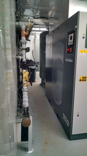
The project included remote operation and monitoring so that the performance could be viewed and adjusted as required. The completed system included a 100 HP variable speed rotary screw compressor capable of providing up to 525 CFM. The compressor automatically adjusts to provide only the air demand needed at any given moment which saves electricity and prolongs the life of the equipment. The System controls display and log temperature, pressure and CFM flow for the compressor and well field areas. The set points and operation timers can be adjusted remotely by phone or computer to maintain optimum efficiency.
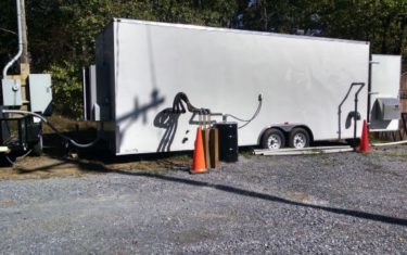
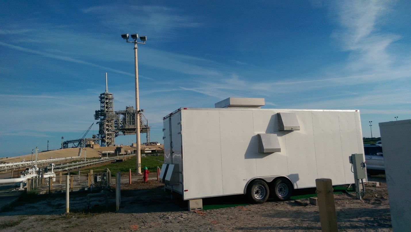
The system was installed in a utility trailer custom designed to handle the size and weight of the compressor. Custom duct-work and climate control were designed to keep the interior of the trailer at the low temperature and low humidity that the compressor requires for proper operation.
This Air Sparge System uses the following components and subsystems
Remediation Site of a Former Gas Station in a Rural Area
MAE2 was selected to design and build a remediation system for a retail gas station based upon the results of a pilot study.
The site is located in a very rural area and only single phase electrical power is available. MAE2 included a Rotary Phase Converter to convert the power to the three phase power needed to operate the larger motors. The site needed three phase voltage in order to meet the NEC, Class 1 Div 2 environment required for equipment operating in the potentially explosive environment created by removing and treating gasoline vapors
MAE2 used the pilot test data to design and provide written specifications for a Multi Phase Extraction and Groundwater Treatment system. The system will use a high vacuum rotary claw pump to extract impacted groundwater and vapors. The groundwater will be treated with an oil water separator to remove free product and then pass through an air stripper and liquid phase carbon to treat the dissolved phase gasoline.
Finally, the system will provide run time hours, vacuum trends, and water flow totals recorded through the PLC control panel. The cellular connection allows full system control and data through easy-to-use web browser access.
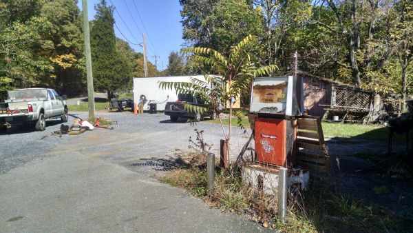
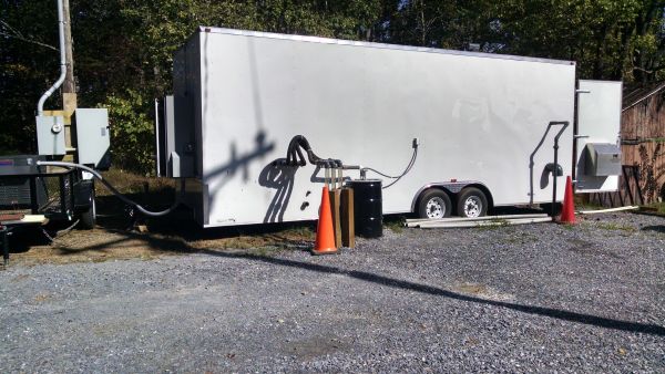
This Gas Station Site remediation System uses the following components and subsystems
Landfill Leachate and Contaminated Groundwater Removal
200 GPM Leachate and Contaminated Groundwater Removal
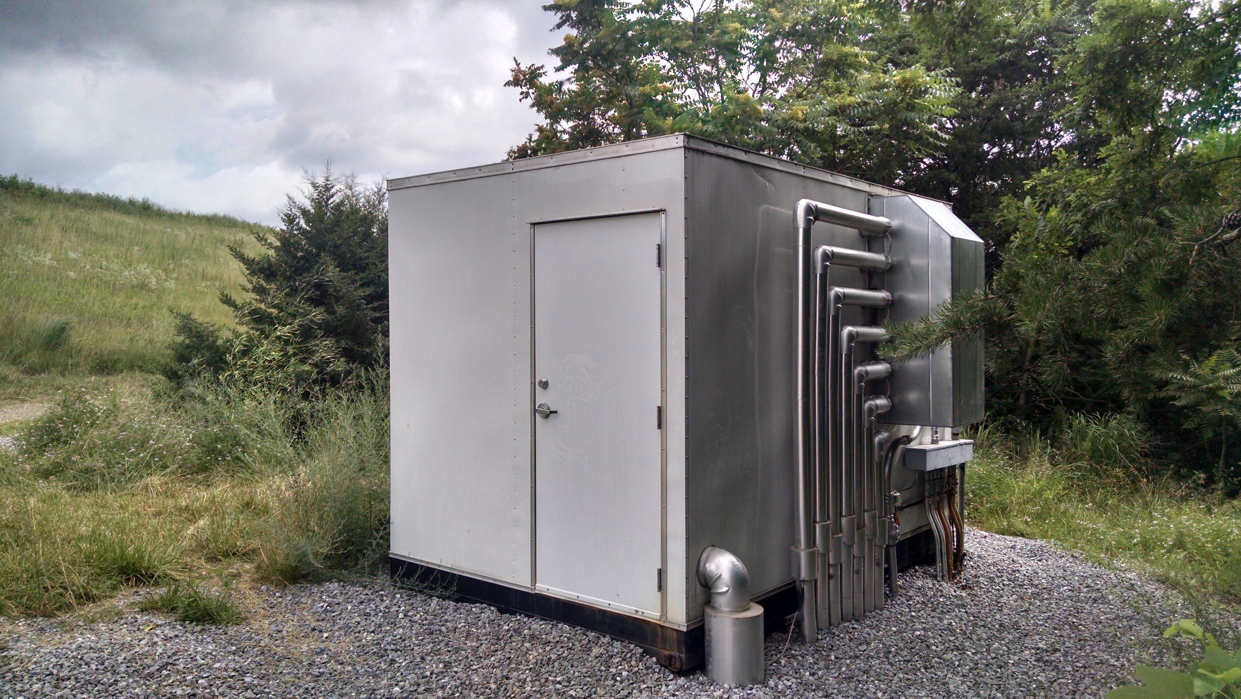
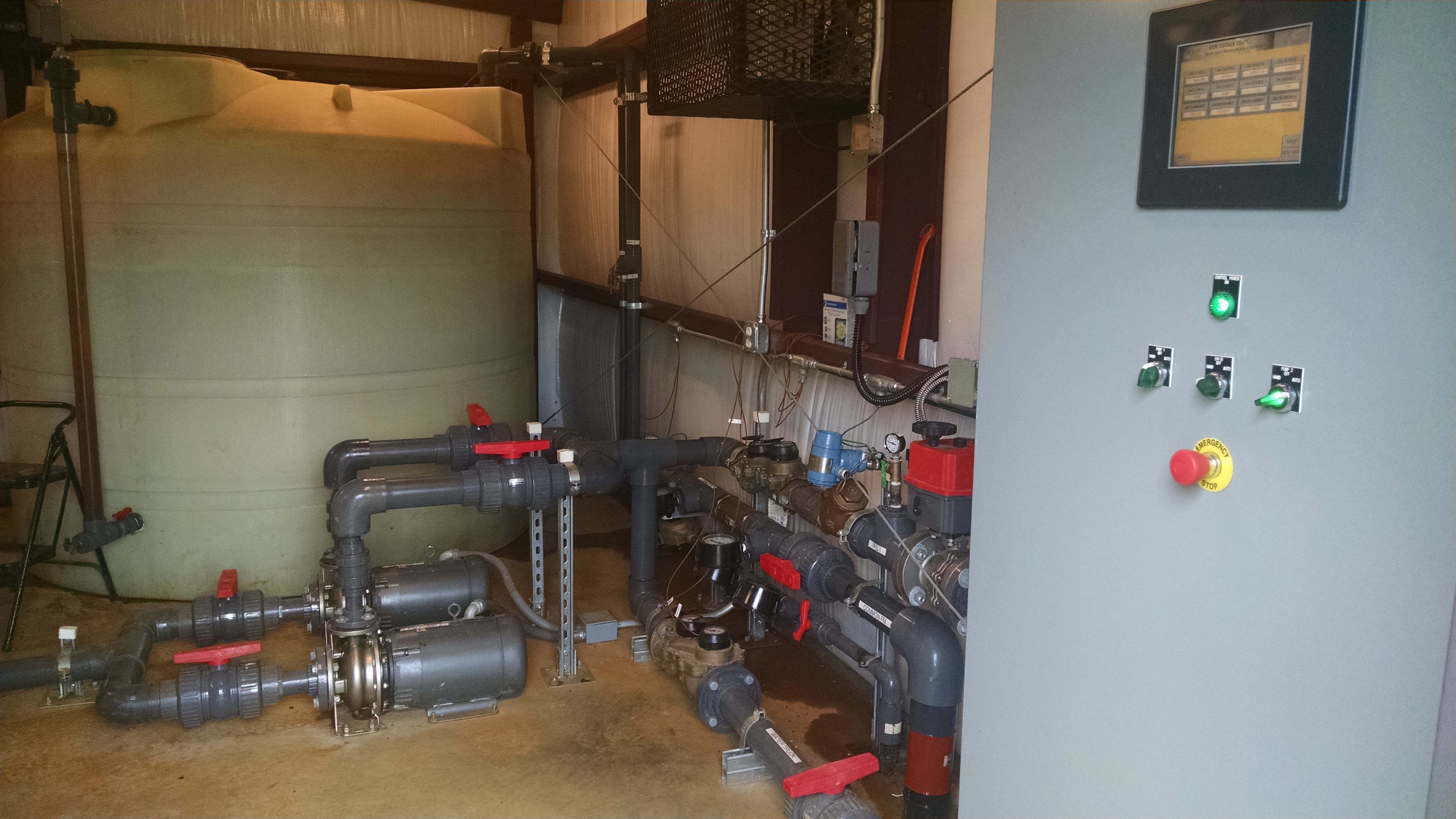
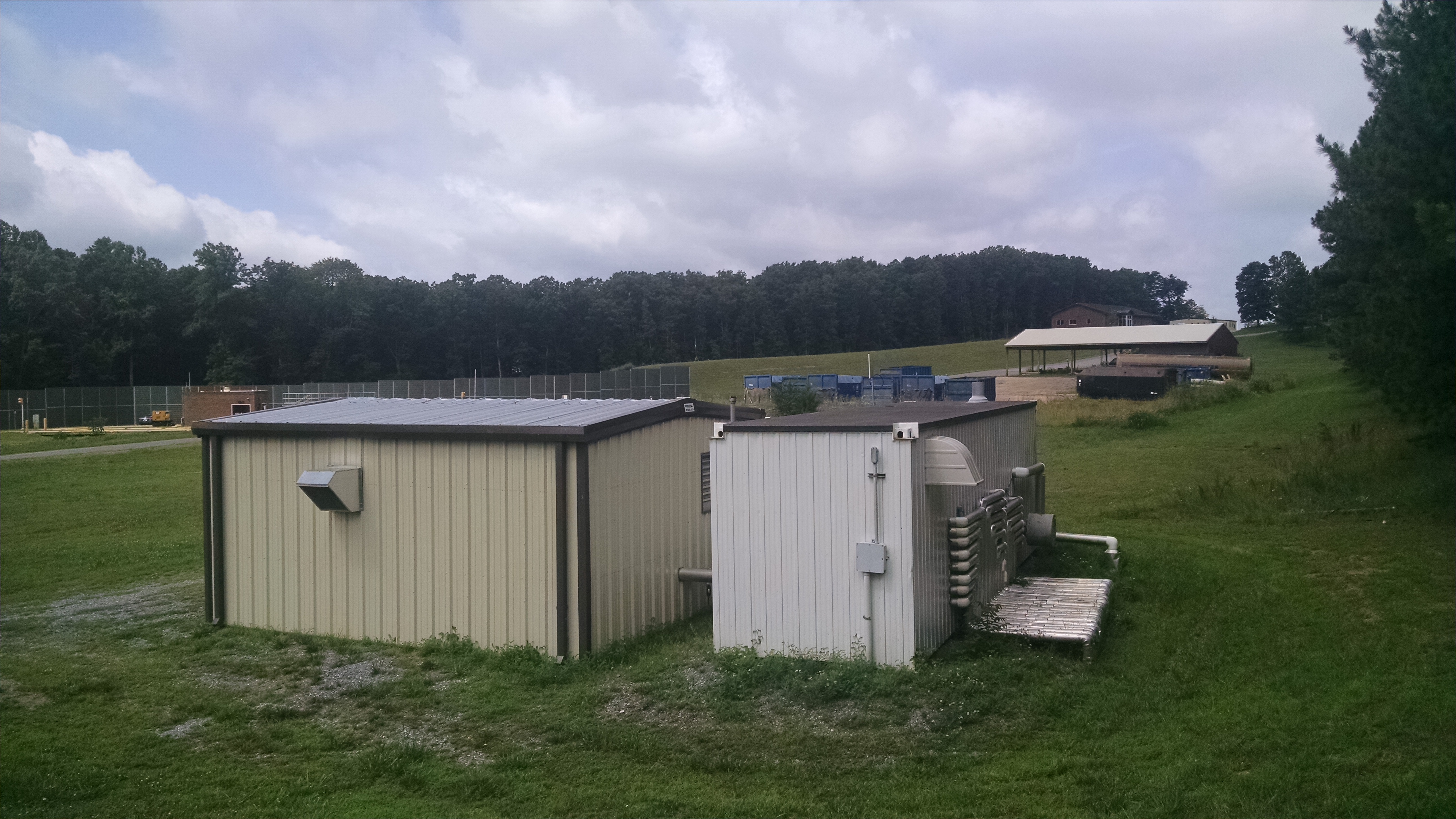
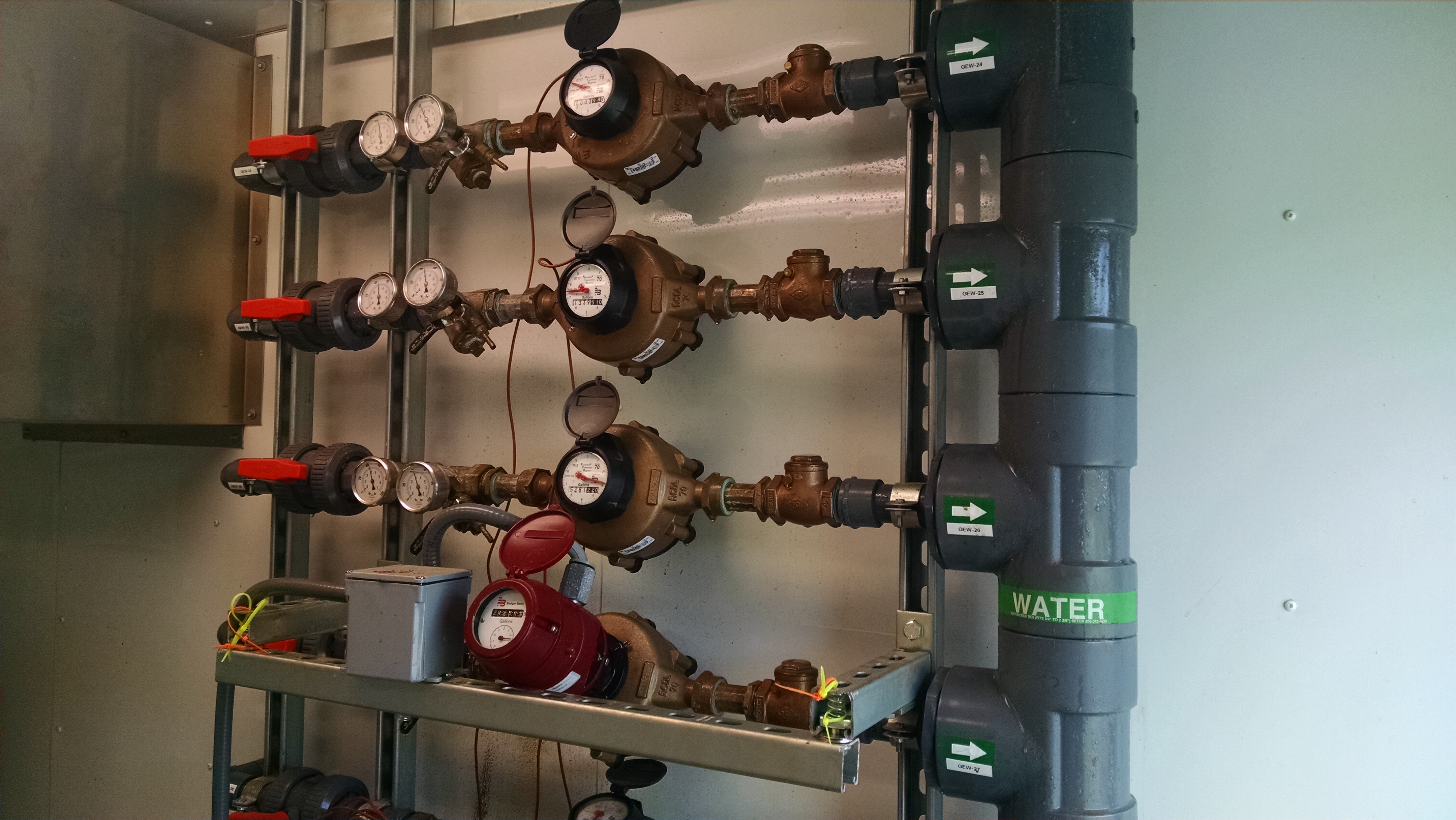
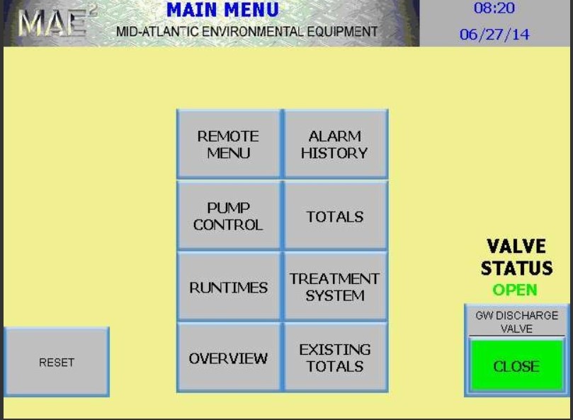
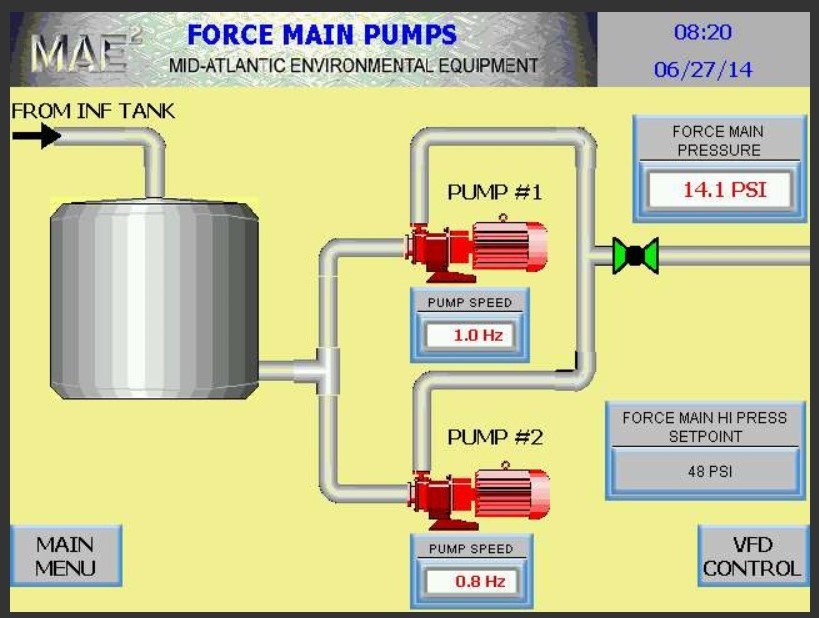
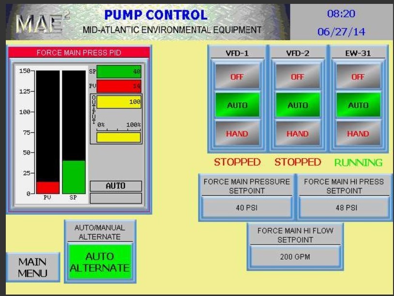
This required a main control panel that provided remote access and control over the groundwater and leachate building while still allowing for local control from each building. The 17 groundwater pumps in the existing building and the 7 leachate pumps in the new building pumped into the main building. The main building contained an 8th leachate pump along with a main holding tank and redundant main discharge pumps capable of operating independently or together as needed. The discharge pumps are controlled using a Variable frequency drive. The total discharge flow is regulated based upon the pressure reading in the discharge line in order to keep the flow within the permit limits as required by the local POTW.
The system is fully automated and adjusts automatically to the incoming flow changes due to rain events and the discharge limitations required by the POTW. The master control panel MCP allows the user to easily adjust the settings controlling the automated operation to meet any changes to the operating conditions as required by permit. The system allows for complete control from each of the on site buildings and also through remote computer access.
This Landfill Leachate and Contaminated groundwater removal systems uses the following components and subsystems
Launch Site Air Sparge System
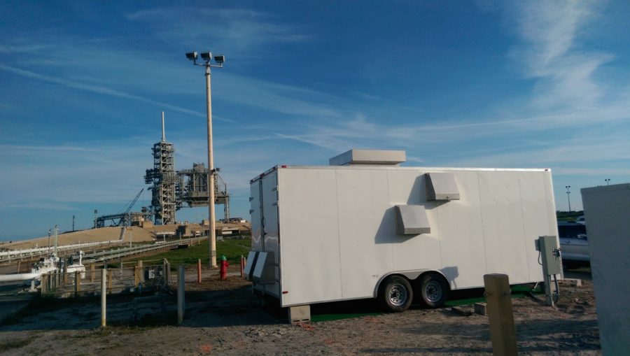
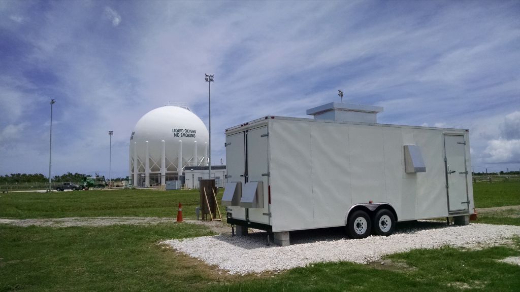
MAE2 was selected to build and start up an integrated Air Sparge system for a site at an aeronautical launch center.
The system was designed to remediate a solvent plume across a large area with dozens of wells. The wells were grouped into 10 zones and the design required that each zone could be easily programmed to operate independently or simultaneous with other zones as needed. The project required remote operation and monitoring so that the performance and the zones could be viewed and adjusted as required. The completed system included a 50 HP variable speed rotary screw compressor capable of providing 50-260 CFM at up to 189 PSIG. The Master Control System (MCP) was designed to provide monitoring of the temperature, pressure and CFM flow for the compressor as well as the individual zones going out to the well field. The MCP allows the user to change the set points and zone operation timers to operate in any combination desired for optimum efficiency. The MCP was connected to internet based access via a cellular modem allowing for complete system control via any web connected computer or from a smart phone. The password protected remote access provides the same control screens and operational control that you get on site from the MCP.
The system was installed in a utility trailer custom designed to meet the equipment operational needs. The axles were oversized to handle the weight requirements of the large compressor. The compressor creates a lot of heat and requires a constant fresh air supply. This required custom ductwork to allow the compressor to receive a fresh clean air supply and to direct all heat and exhaust to the outside of the trailer. Custom washable filters were designed for easy maintenance of the duct work. The system was build with a split unit air conditioner to keep the summer temperatures from causing system shutdowns. To save energy during the winter months the system included a simple vent fan and fresh air louver with lockable covers to prevent air loss when the air conditioner is needed.
This Air Sparge System uses the following components and subsystems
Marine Research Groundwater Treatment System
Variable Flow Industrial Process Treatment System
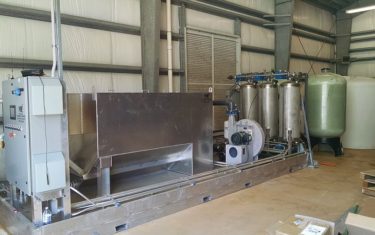
MAE2 was tasked with designing a system to treat process water to remove iron and fuel contamination for a marine research center. The research center used local groundwater to supply fresh water to fish tanks used for scientific research. The groundwater had been impacted with fuel from a nearby gas station and was high in iron bacteria. The fuel needed to be removed from the water to keep the fish healthy and the iron needed to be removed to keep it from fouling the drum filters that provided the filtered water required in the tanks. The system needed to handle flows that ranged from 8 GPM to peak flows of 45 GPM. The facility wanted to reduce electrical power costs by only operating at full power during peak times and adjusting the power down during lower flow periods.
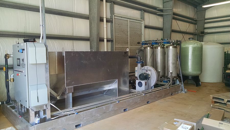
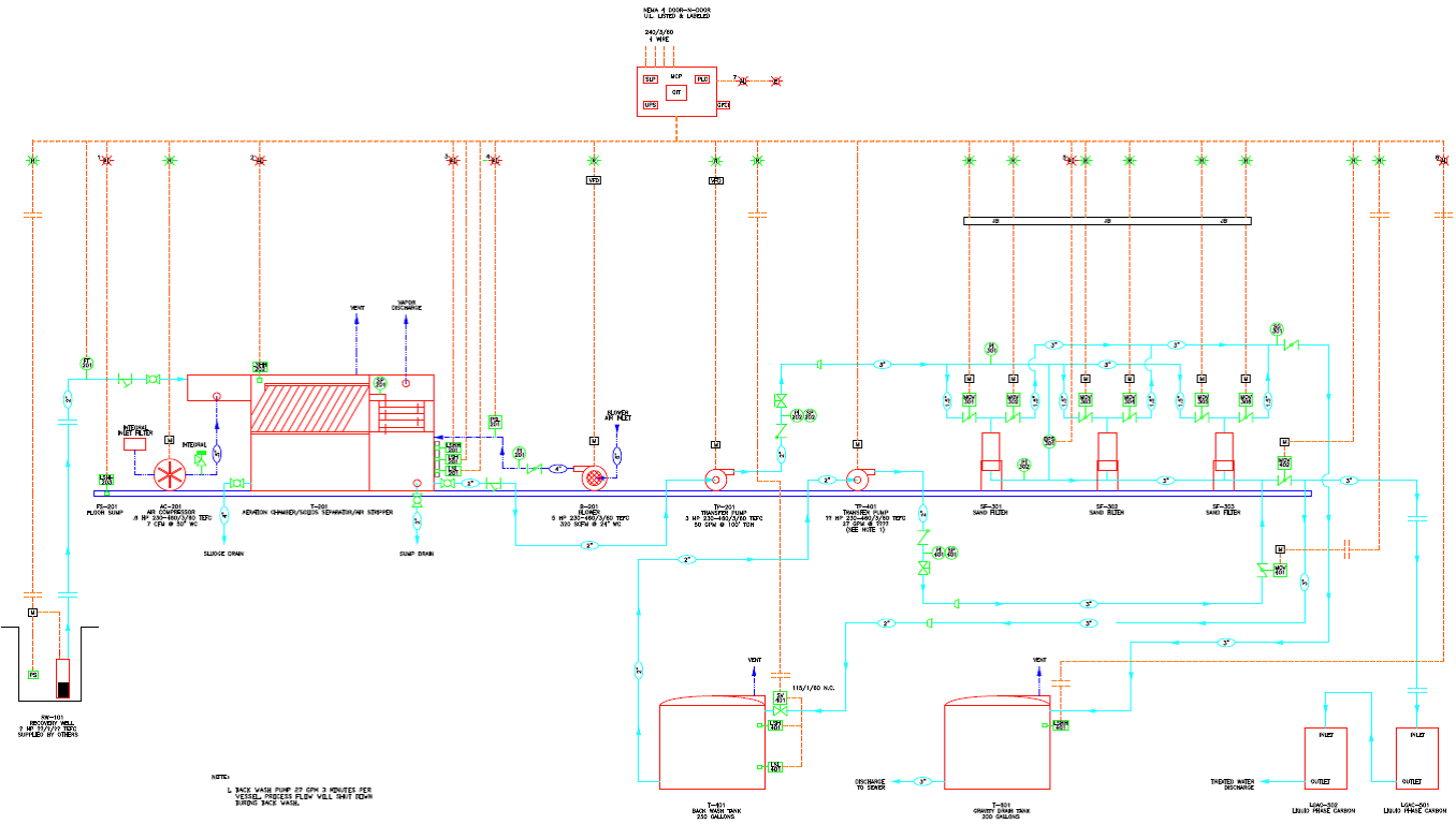
MAE2 designed a system with a fully automated PLC control panel. The PLC constantly measures the incoming flow rate and uses Variable Frequency Drives (VFDs) to adjust the motor speeds to match the flow rate. The PLC controls also monitor system pressures and automatically initiates a system backwash to clear the iron filters and reduce manual cleaning labor. The system is designed to keep a continuous water supply to the research tanks even during the back wash cycles.
This turnkey MAE2 solution reduces on site maintenance, electrical power usage, and provides treated process water in a compact fully automated package that adjusts to the constantly changing site conditions. This system is expected to go online this upcoming summer.
Click on diagram to see another.
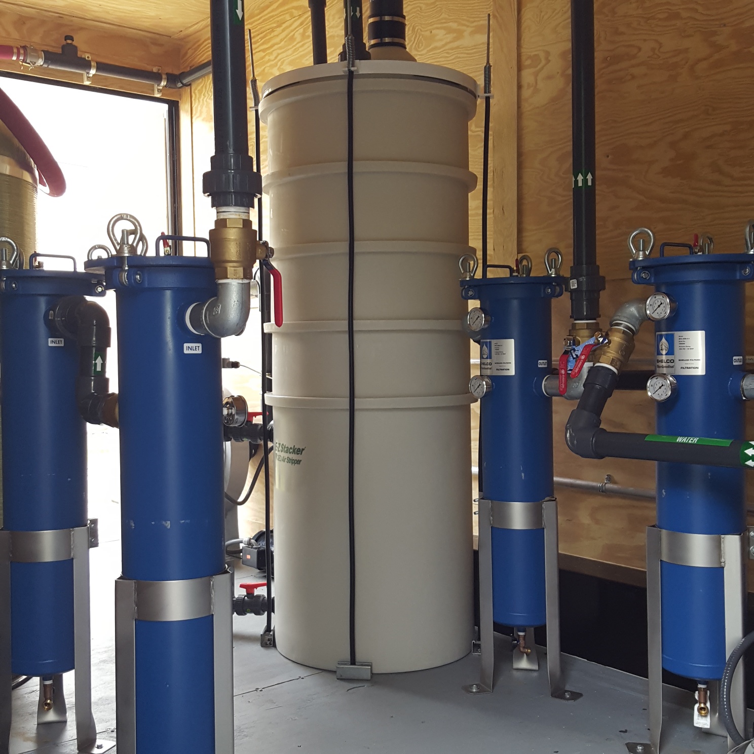
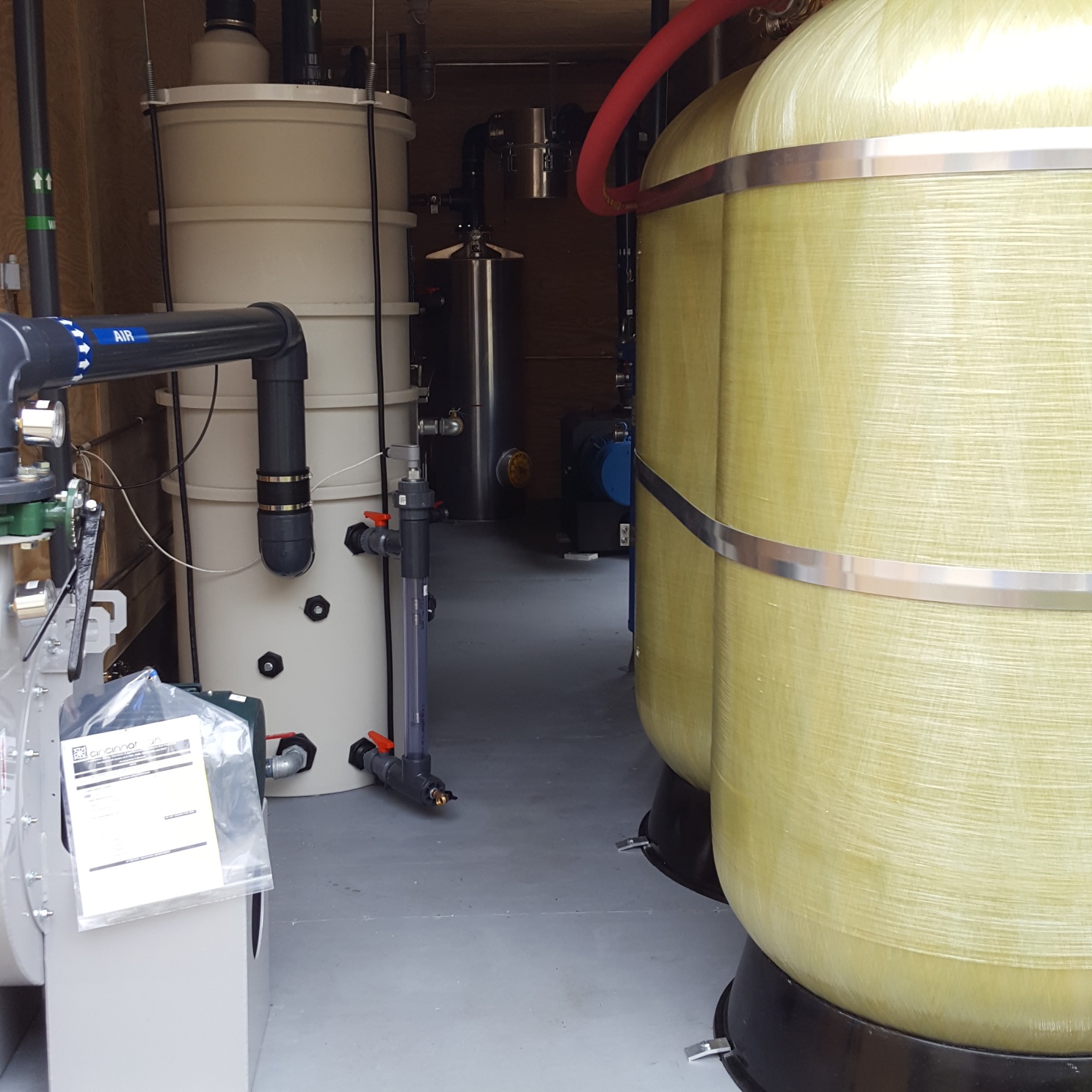
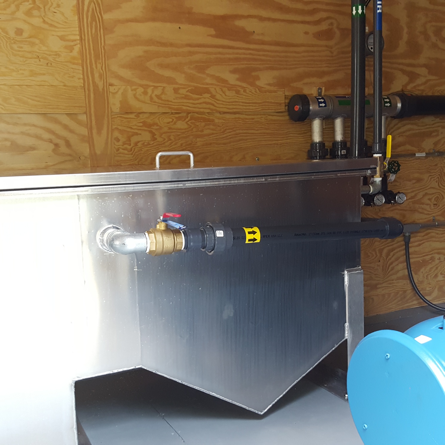
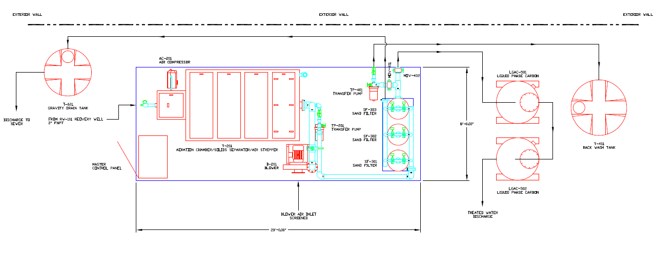
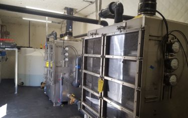
The groundwater treatment system consisted of an aeration chamber and slant plate clarifier to precipitate and collect iron, a removable tray air stripper to remove the dissolved gasoline, a back-washing filtration media system to remove any fine particulate and finally liquid carbon media vessels as a final safety to remove any potential remaining gasoline.
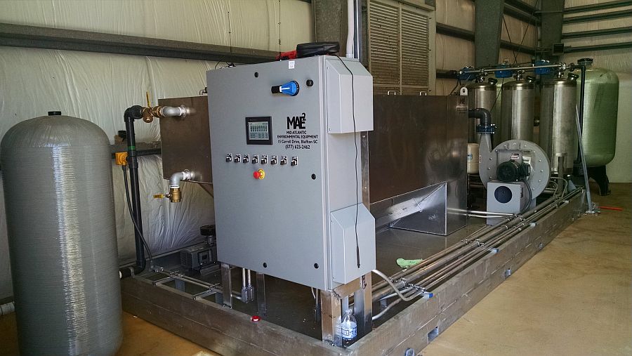
This Marine Research Groundwater Treatment System uses the following components and subsystems
Chlorinated Solvents Removal with 10 Remote Wells
Soil and groundwater remediation using a 300 gallon per minute treatment system connected to 10 remote recovery wells
PROBLEM: Local water table contaminated with chorinated solvents over a period of 40 years.
SOLUTION: MAE2 was tasked with the construction of a 300 GPM ground water treatment system to remediate a Chlorinated solvent plume at a manufacturing facility in South Carolina. The facility site is approximately 65 acres and located in a mixed industrial, residential area. The treatment area included the site property and other areas extending ¼ – ½ mile down gradient of the plant.
The project required remote communication with 10 recovery wells from a centralized control panel located at the treatment facility.
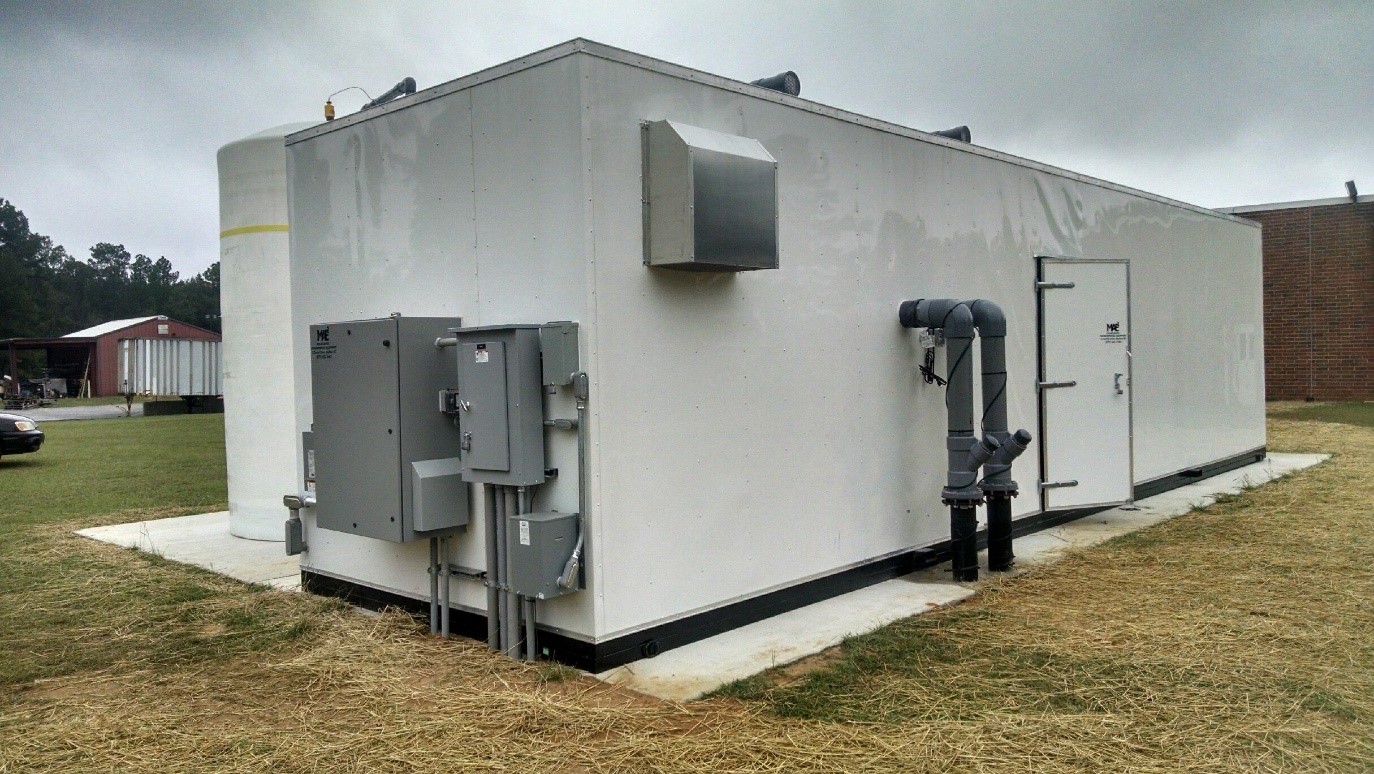
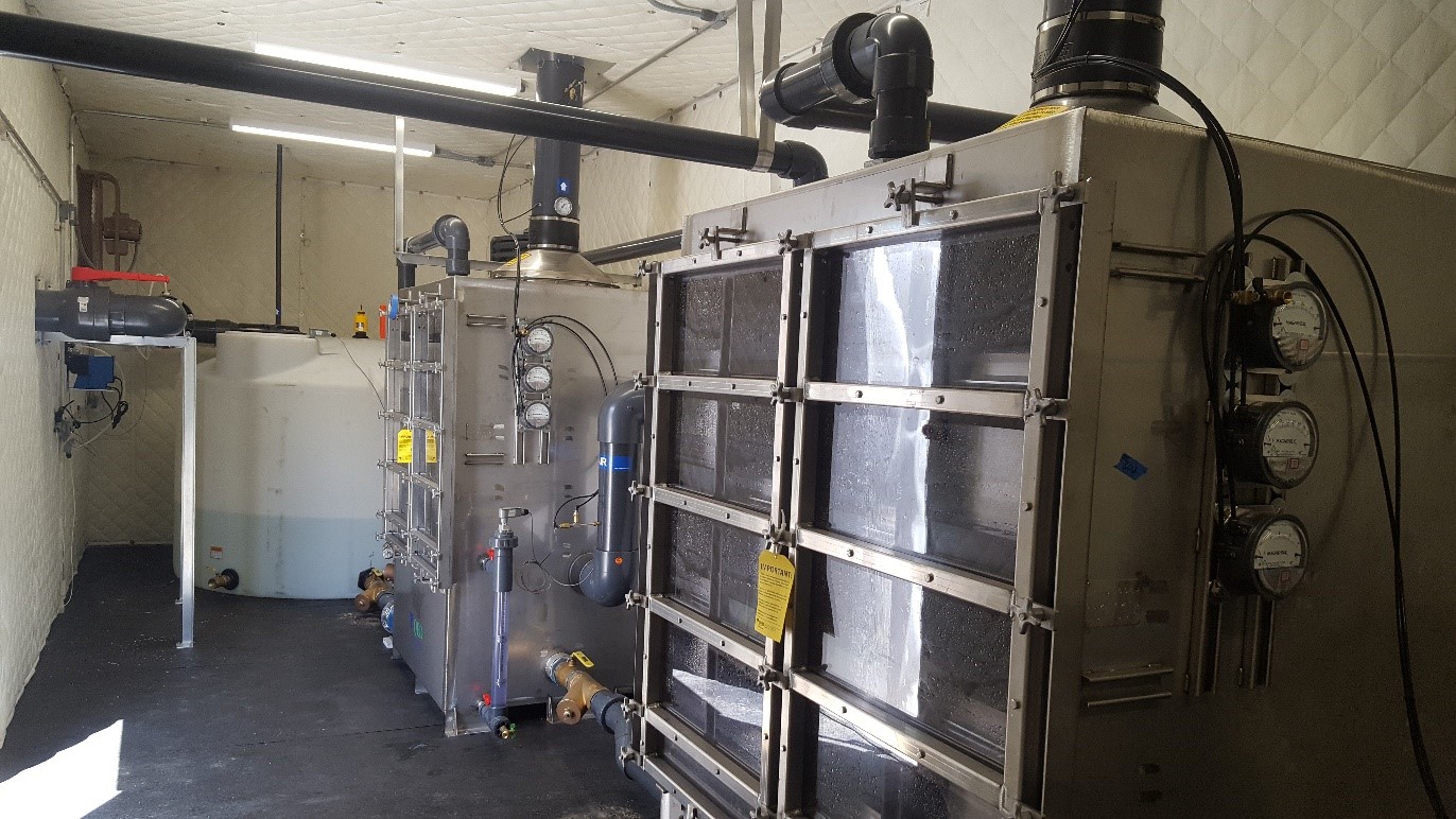
The treatment system was constructed in a prefabricated 10 x 40’ steel frame building and consisted of an equalization tank, pH adjustment, tandem 150 GPM stainless steel tray air strippers, bag filtrations and PLC controls.
The well field consisted of 10 extraction points, each with a 3 HP electric submersible pump placed approximately 200’ below grade. Each of the pumps had local PLC controls to power the pump and provide the communications loop back to the Main Control Panel (MCP) at the treatment system.
In addition, each well included submersible transducers, water flow transmitters and positioning ball valves all controlled by the MCP to maintain a constant water level in the recovery wells. Due to the distance of the wells from the main treatment system, fiber optic cable was chosen as the means of data communication between the well field controls and the MCP at the treatment system.
This is a large project that has been in preparation for about 8 years! The first demonstration tests took place August 2016, and the project will last about 20 years before remediation is complete!
Chlorinated Solvents Removal
The extracted groundwater required treatment before it could be discharged. The discharge water is used to fill a 2,000 gallon tank and used to support the chiller units used at the factory. The water not used by the facility is discharged to the local storm water network.
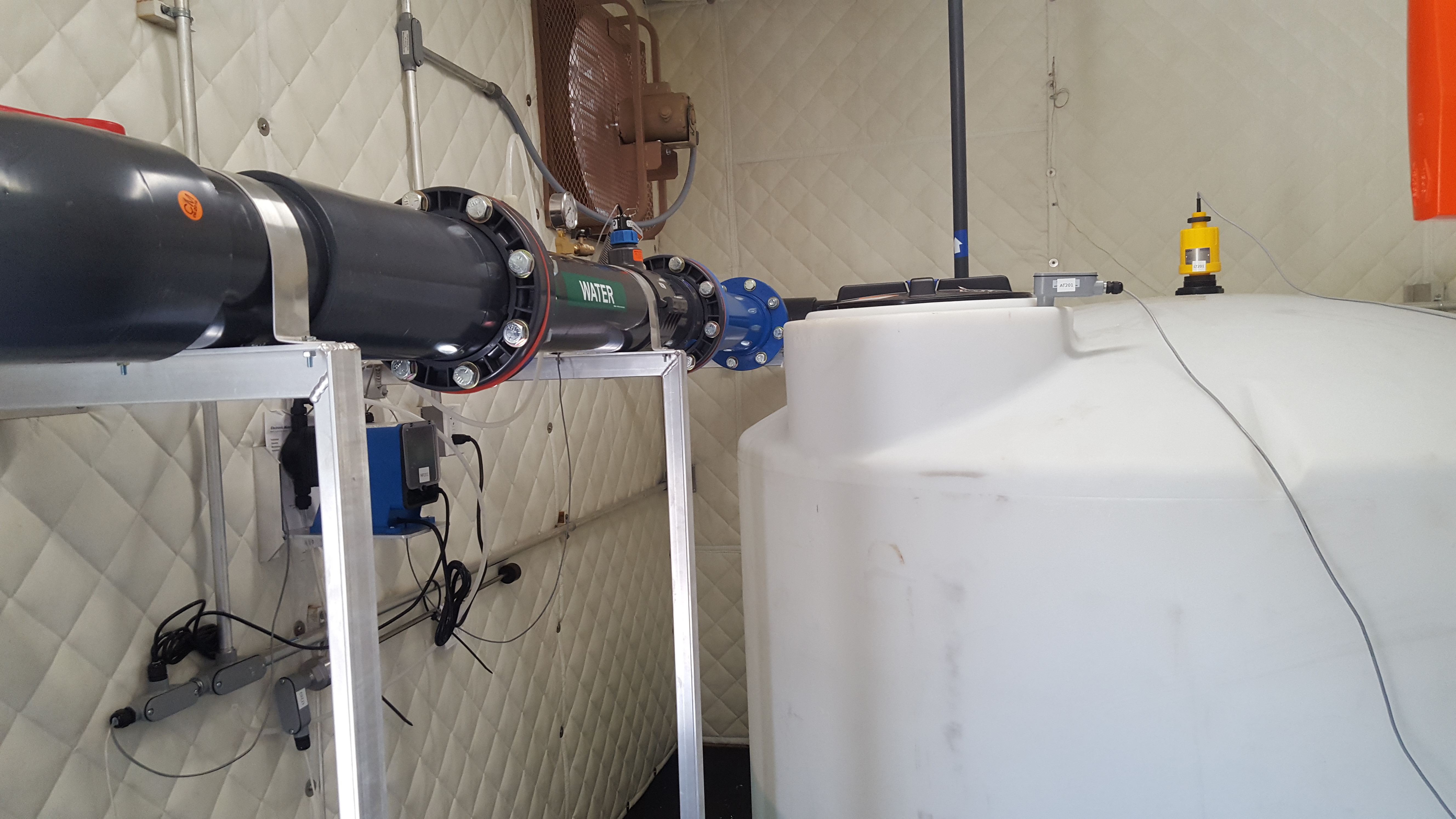
In order to meet the discharge requirements all chlorinated solvents and any suspended solids had to be removed. The influent water is pumped into an equalization tank where caustic was added to adjust the pH so that the treated water could be discharged.
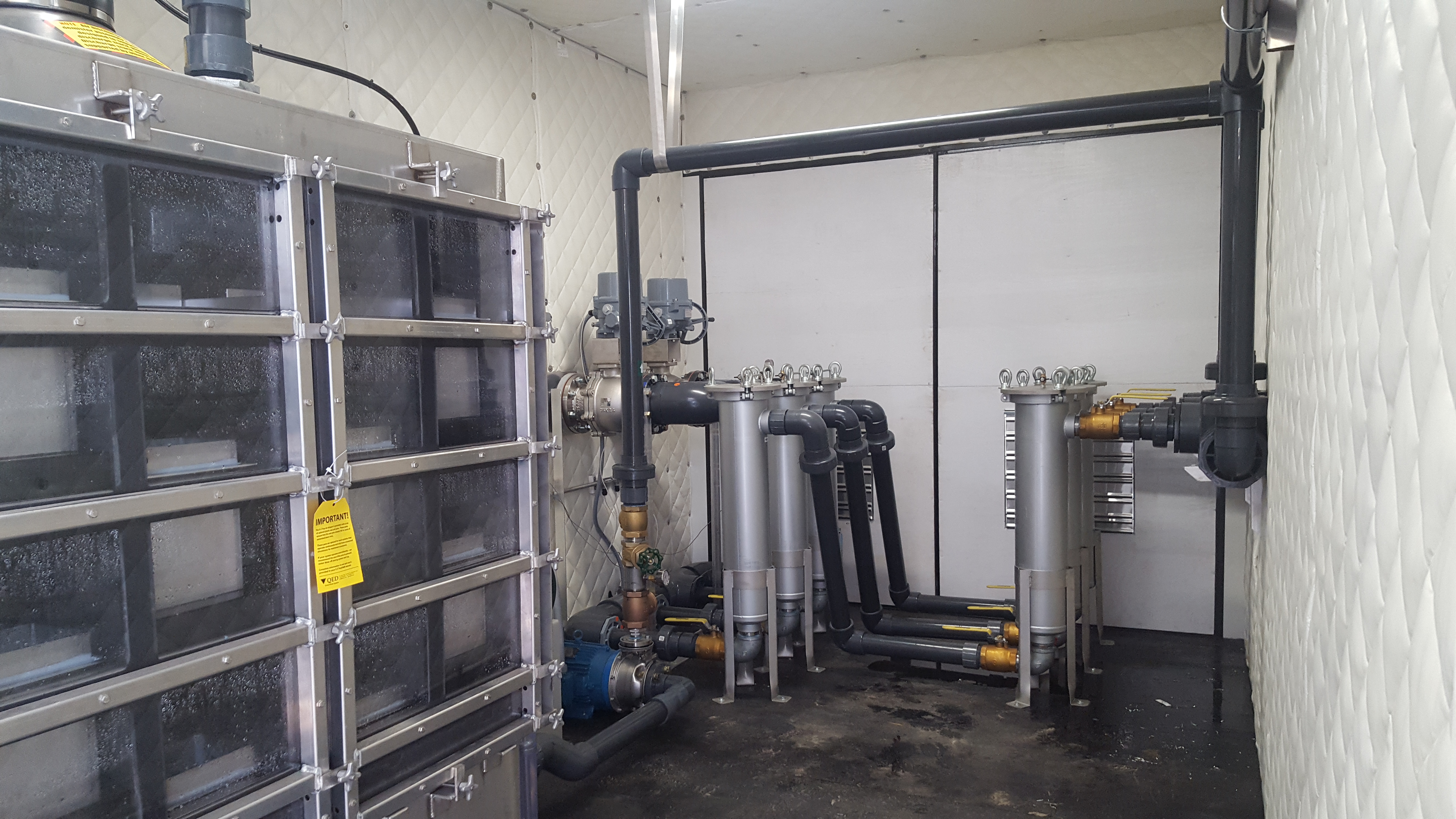
Two 250 GPM removable tray air strippers were installed in parallel. Each Air Stripper has 6 removable trays that provide plenty of residence time to strip the solvents from the groundwater. Each air stripper has a 10 HP pressure blower to provide the air to water ratio needed to clean the water and a 10 HP centrifugal transfer pump. Any suspended solids or other particulate is removed from the air stripper discharge by two sets of 3 bag filtration vessels plumbed in series.
The clean water then leaves the groundwater remediation building and is directed through an automated valve to either the chiller holding tank or the storm water system as needed.

