Multi Phase Extraction at a Bulk Fuel Terminal
MAE2 was asked to provide a bid for an environmental remediation project to clean up the groundwater and soil at a Bulk Fuel terminal for a Major Oil Bulk Fuel facility.
MAE2 was selected after a thorough review determined that the equipment and pricing proposal, for a Multi Phase Extraction system represented the most responsive and cost effective solution for the site.
The site clean-up goals required draw-down of the site groundwater followed with high vacuum Soil Vapor Extraction to clean the soils in the vadose zone and dewatered saturated soils. The water is to be treated to meet standards for surface water discharge. The contaminated vapors are to be treated using an electric oxidizer.
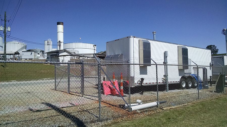
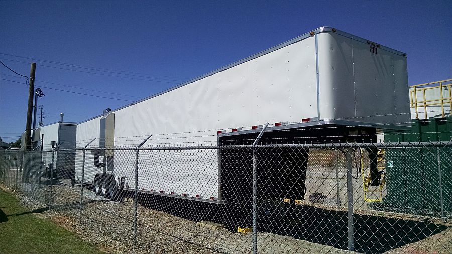
The Multi Phase Extraction system design is for the equipment to be contained in two enclosed cargo trailers. The use of two trailers allows for flexibility to locate and move the system around the site as needed.

Trailer 1 Multi-Phase extraction system
Trailer 1 is a two room trailer that contains the main system control panel and a rotary screw compressor in an air conditioned non hazardous room. The air compressor provides the air supply required to operate eight downwell pneumatic pumps. Room 2 includes the air supply manifold for the pneumatic pumps and the extraction manifold SVE wells. Two 15 HP rotary claw vacuum pumps provide up to 730 ACFM at 25” HG. Any moisture and groundwater extracted is collected in the Vapor liquid separator and is then pumped over to the groundwater treatment system housed inside trailer 2 using a progressive cavity transfer pump. The extracted vapors are treated with a 600 SCFM electric oxidizer located within room 2. The oxidizer uses an automated vapor control valve to automatically adjust the vacuum to keep the vapor concentrations within the treatment range for complete destruction. Room 2 is designed to meet Class 1 Div 2 standards for hazardous locations and also includes a high LEL alarm that shuts the system down if explosive vapors are present.

Trailer 2 Multi-Phase extraction system
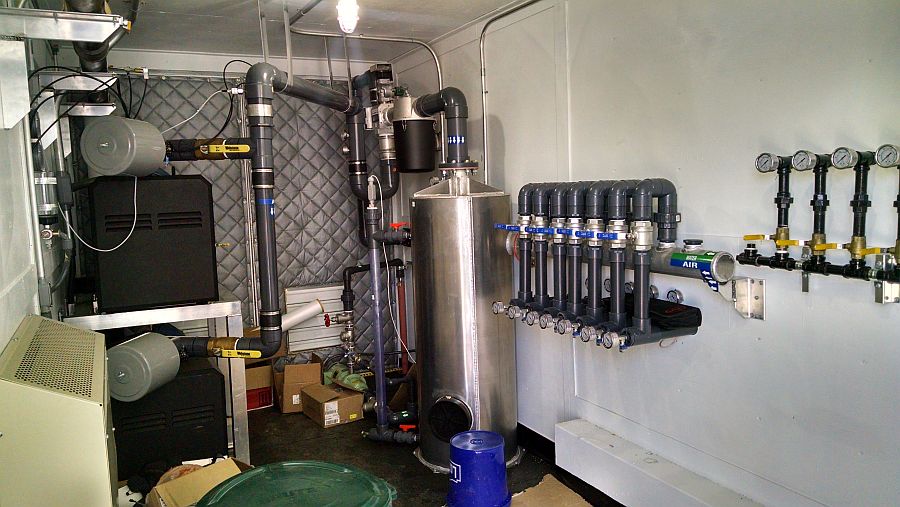
Trailer 2 contains the groundwater treatment system designed treat water at flows up to 60 GPM. The trailer 2 interior is built to Class 1 Div 2 standards for hazardous locations. There is a groundwater influent manifold that allows individual well control and has a flow transmitter for each leg that records gpm flow and total gallons on the PLC control panel display. An explosion proof chemical metering pump injects into the manifold header discharge to treat the water to prevent iron scaling. The groundwater flows into a cone bottom separator tank to collect any solids and allow any free gasoline to separate to the top. Water then flows into a large EQ tank and is pumped through bag filters to remove sediment to a removable tray air stripper using a centrifugal transfer pump. From the air stripper the water is pumped through two 750 LB steel carbon vessels and then to discharge. The trailer is designed with waterproof floor and a waterproof containment equal to 110% of the holding tank volume. The trailer has a floor sump alarm to shut the system down in case of a water leak and similar to trailer 1 has a high LEL alarm.

Components of the Multi-Phase extraction system
Each trailer has its own PLC control panel with a color touch screen display. The control panels are connected via an Ethernet communication cable. An operator can access either control panel from each individual panel screen or from a remote internet connection. The control panel allows each system to operate independently or to be interlocked together and records all alarms, flows, pressures and vacuum. Alarms notifications are sent via email or text and the system can be accessed remotely through a web based connection.
This Environmental Remediation System uses the following components and subsystems
Progressive Cavity Transfer Pump
Chemical metering pump
